Category: Structural mechanics

  • FEM-Simulation von Klebeverbindungen – Präzise Spannungsanalyse für sichere Fügetechnik

    FEA Simulation of Adhesive Bonds – Precise Stress Analysis for Secure Joining Technology

    Adhesive bonding is playing an increasingly important role in modern constructions – from aerospace and automotive engineering to wind turbines and general mechanical engineering. In contrast to form-fitting connections such as screws or rivets, adhesive bonds transmit loads over an area, reduce notch effects, and enable the joining of diverse materials. This makes reliable computational assessment all the more important – especially with the Finite Element Method (FEM).

    FE Modeling of Adhesive Joints

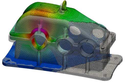
    Similar to bolted connections, adhesive bonds can also be precisely considered in FEM models. We use a modeling technique that not only correctly maps global load transfer but also enables a sufficiently detailed assessment of stresses within the adhesive layer itself. This reliably identifies and evaluates critical areas such as adhesive layer edges, overlap zones, and peel stress peaks.

    Why is correct FEM modeling of adhesive layers crucial?

    The adhesive layer is the mechanically critical element of the bond, despite its often small thickness. Simplified or neglected modeling frequently leads to:

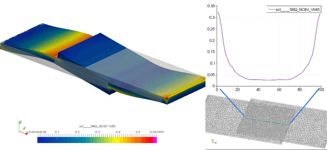
    • Underestimation of peeling stresses at the edges of the overlap – one of the most common failure mechanisms for adhesive bonds
    • Faulty stiffness mapping of the overall system, especially with hybrid constructions made of metal and fiber composite materials
    • Inadequate assessment of fatigue loads, which can lead to creeping failure of the interface under cyclic loading
    • Overlooking residual stresses from the curing process, which significantly affects the effective load-bearing capacity

    Our modeling strategy in detail

    Depending on the requirements and available computing power, we use different, coordinated modeling approaches:

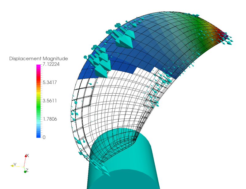
    • Volume elements for the adhesive layer enable direct, three-dimensional stress evaluation within the adhesive, particularly for normal and shear stress components
    • Cohesive Zone Models (CZM) represent the progressive failure of the interface and are suitable for fracture mechanics and delamination analyses
    • Tie-constraints and surface-to-surface contacts – for efficient modeling in system simulations with many joining partners
    • Material Models for Adhesives – from linear-elastic through viscoelastic to elastoplastic, adapted to the respective adhesive type (epoxy resin, polyurethane, acrylate, etc.)

    Evaluation criteria and proof of failure

    Based on the FEM results, we perform a structural mechanics assessment according to recognized codes and internal methods:

    • Stress-based detection of shear, peel, and normal stresses in the adhesive layer
    • Comparison with adhesive properties from data sheets or own tests (e.g., tensile shear test according to DIN EN 1465)
    • Safety evidence against cohesive and adhesive failure
    • Consideration of temperature influences on adhesive properties (glass transition temperature, thermal expansion)

    Typical application areas

    Our FEM-based adhesive joint analysis is used in many industries and components:

    • Structural Adhesions in Lightweight Construction – Aluminum-CFRP Hybrid Joints, Sandwich Structures
    • Wind turbines – Rotor blade bonding and flange connections
    • Automotive engineering – body stiffeners, windshield bonding, battery enclosures
    • Mechanical and apparatus engineering – Adhesive bonding for bearings and seals under mechanical and thermal loads
    • Electronics and Medical Technology – Miniaturized Adhesive Bonds with High Reliability Requirements

    Simulate adhesive bond now

    Do you want to computationally verify the load-bearing capacity of an adhesive bond or expand an existing FEM model with a realistic adhesive layer modeling? Contact us.

  • FEM-Simulation mit Code_Aster – Über 10 Jahre Erfahrung in der Strukturanalyse

    FEM Simulation with Code_Aster – Over 10 Years of Experience in Structural Analysis

    Code_Aster is one of the most powerful yet demanding open-source finite element codes worldwide, developed and continuously maintained by the French energy company EDF. With a feature set that surpasses many commercial FEM programs, Code_Aster is particularly well-suited for complex structural, thermal, and coupled analyses in industrial and scientific environments.

    We have more than 10 years of practical experience in the professional use of Code_Aster and use this FEM code for a wide spectrum of demanding calculation tasks – from simple static analysis to highly complex transient simulations with nonlinear material behavior and contact.

    Our services with Code_Aster at a glance

    Static and transient structural analyses

    Whether it's operating load, impact, or time-varying loads – we calculate the mechanical behavior of components and structures under realistic load conditions. We utilize the full range of element types offered by Code_Aster:

    • Volume elements – for massive components, welds, and complex 3D geometries with detailed stress analysis
    • Shell elements – for thin-walled structures like sheet metal, containers, pipelines, and housings with high computational efficiency
    • Stab and beam elements – for frame structures, steel structures, and system models with many degrees of freedom

    Contact problems and nonlinear analyses

    Contact problems are among the numerically most challenging tasks in FEM. Code_Aster offers robust algorithms for this purpose, which we specifically employ for issues such as press fits, bonded joints, sealing surfaces, or the lifting of components under operational loads. Geometric and physical nonlinearities – such as large deformations or elastoplastic material behavior – are also accurately represented.

    Screwed connections

    The realistic modeling of bolted connections in FEM models requires both methodological know-how and experience with the peculiarities of the respective solver. We simulate pretension forces and the elastic behavior of bolted connections using proven methods – for reliable validations according to common standards such as VDI 2230.

    Eigenfrequency analysis and modal analysis

    Knowledge of the natural frequencies and mode shapes of a structure is a prerequisite for assessing resonance risks and designing vibration-damped constructions. With Code_Aster, we perform modal analyses and, if necessary, combine them with harmonic or transient vibration response calculations – for example, for rotating machinery, piping systems, or seismically stressed installations.

    Why Code_Aster – and why with us?

    • No licensing cost overhead Code_Aster is open source under the GPL license and enables cost-effective calculations even with high computational volumes or parallel projects.
    • High solver quality The code has been used and validated by EDF for safety-critical applications in nuclear engineering and power supply for over 30 years.
    • Reproducible, documented results – all simulations are built in a traceable manner and completed with engineering evaluation of the results

    Typical Industries and Application Areas

    Our Code_Aster projects span numerous industrial and engineering fields:

    • Mechanical and plant engineering – stress analysis for pressure vessels, flanges, welded constructions
    • Energy and Process Engineering – Piping Analyses, Heat Exchangers, Vessel Design
    • Vehicle and Rail Vehicle Technology – Crash-Relevant Structures, Durability Proofs
    • Aerospace – Lightweight structures with fiber composite materials and adhesive bonding
    • Construction and Infrastructure – Seismic Analysis, Steel Construction, Foundation Verification

    Requesting FEM calculation with Code_Aster

    Are you looking for an experienced partner for structural mechanics calculations with Code_Aster? Contact us – we will discuss your task and jointly develop an efficient and robust simulation strategy.

  • Fluid-Struktur-Kopplung für Composite-Propeller: CFD mit OpenFOAM und Code_Aster

    Fluid-Structure Coupling for Composite Propellers: CFD with OpenFOAM and Code_Aster

    Modern fiber-reinforced composite ship and flow propellers offer significant advantages over traditional metal propellers – lower weight, improved cavitation properties, and the possibility of passive pitch adjustment through targeted anisotropy. However, their flexibility presents particular design challenges: the aerodynamic or hydrodynamic performance can only be correctly assessed if the structural deformation under operational load is included in the simulation.

    Composite Propellers: Opportunities and Design Challenges

    Propeller with wings made of Fiber composites – especially those made of carbon fiber-reinforced plastic (CFK) or glass fiber-reinforced plastic (GFK) – are elastically deformable under operating loads. This flexibility is not a design flaw, but can be used strategically:

    • Passive pitch adjustmentThrough targeted fiber orientation, the wing twists into a more favorable airflow as the load increases – automatically, without active mechanics.
    • Cavitation reductionThe adjustment of the blade geometry under load can smooth out pressure peaks, thereby reducing the risk of cavitation.
    • Noise reductionReduced pressure pulsations through optimized load distribution over the blade
    • Weight savingsCFK propellers are significantly lighter than bronze or stainless steel propellers of the same stiffness.

    The flip side: When interpreting, you must consider Deformation of the wings under operating load must be taken into account.. A purely rigid CFD simulation would systematically mispredict the actual geometry in operation—and thus thrust, torque, and efficiency.

    What is Fluid-Structure Interaction (FSI)?

    The Fluid-Structure Interaction (FSI) describes the interaction between a flowing fluid and an elastic structure. In the case of a composite propeller, this means:

    • The Fluid (water or air) exerts thrust on the propeller blades
    • The Structure deforms elastically as a result of these forces
    • The altered geometry in turn influences the Flow – and thus the pressure distribution
    • This cycle will iterative until convergence solved

    Depending on the stiffness of the structure and the strength of the flow forces, this coupling effect can be small and negligible—or so dominant that it fundamentally determines the design. With flexible composite propellers, the latter is usually the case.

    Our Software Solution: OpenFOAM + Code_Aster Fully Coupled

    We have a specialized Software solution for FSI simulation of composite propellers developed a solution that combines two leading open-source programs into a powerful, fully automated workflow:

    • OpenFOAM The CFD simulation handles: calculation of the flow field, pressure distribution, and hydrodynamic forces on the propeller blade – including rotating mesh regions (MRF or Sliding Mesh).
    • Code_Aster addresses the structural mechanics aspect: finite element analysis of the anisotropic composite material under the applied fluid forces, calculation of deformations and stresses in the laminate
    • An Matching algorithm transfers forces and displacements between the two solvers and updates the CFD mesh in accordance with the structural deformation (dynamic mesh morphing)

    Both tools are completely open-source – with no licensing costs, full transparency, and maximum adaptability to specific project requirements.

    Technical Features of Our FSI Solution

    • Anisotropic Material Modeling: Code_Aster models the laminate structure of CFRP and GFRP composites layer by layer—including direction-dependent stiffness and strength properties
    • Cavitation modeling: Optionally, the FSI simulation can be extended to include a cavitation model in order to capture the interaction between phase change and blade deformation
    • Automated workflow: The entire simulation workflow—meshing, solver setup, coupling, and post-processing—is script-driven and reproducible within the InsightCAE framework

    Results and key figures from the FSI simulation

    From a complete fluid-structure interaction simulation for composite propellers, you will obtain, among other things:

    • Thrust and torque characteristics considering the actual operating geometry
    • Displacement field (from which deflection, twist, torsion) over the entire propeller blade
    • Stress and Strain Distributions in Laminates – Basis for Strength Verification according to Puck, Tsai-Wu, or Similar Criteria
    • Pressure distribution on the suction and pressure sides of the wings
    • Cavitation index and cavitation propagation (with extended modeling)
    • Efficiency and operating point stability across the entire characteristic curve range

    Areas of application

    Our FSI solution for composite propellers can be used in the following areas:

    • Carbon fiber or glass fiber ship propellers for high-performance and sports boats
    • Underwater drones and AUV propulsion with noise emission or lightweight requirements
    • Wind turbine rotor blades (small wind turbines, vertical axis systems)
    • Tidal stream turbines with flexible composite blades
    • Research applications for validating FSI algorithms

    Conclusion: Precise propeller design through physically consistent FSI simulation

    Those who design composite propellers with rigid CFD risk systematic errors in performance prediction and structural design. Our coupled simulation solution, based on OpenFOAM and Code_Aster, closes this gap – cost-efficient, transparent, and fully automated. This allows you to design composite propellers as they actually work: deformed, stressed, and performance-optimized.

    Are you developing a composite propeller and need a robust FSI simulation? Contact Us We guide you from geometry to the validated result.