
Author: Hong Kong
-
Our Services
InsightCAE
We implement automated calculation processes according to your wishes and specifications. We can easily provide and maintain these as add-on modules to InsightCAE,
Thereby
- you speed up your daily work,
- errors due to incorrect operation are avoided,
- complicated tasks can also be carried out by inexperienced colleagues
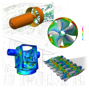
Some examples of apps we have developed for our clients:
- Ship Resistance Analysis by CFD
- CFD for flooding of ship hulls
- Maneuvering of Ships with Controlled Rudder and Seaway using CFD
- Performance Analysis of Sailing Rigs Using CFD
- Seakeeping behavior of ships using frictionless theory
- Roll Damping of Ships Using CFD
- Thermal Analysis of Brakes
- Marine Propeller and Propulsion
- Plate heat exchanger
- Gas dispersion
- Ventilation for air conditioning of industrial halls and buildings
-

InsightCAE – Documentation
The documentation can be found here: InsightCAE Manual.
The sources of the LaTeX document are found on Github.com: InsightCAE Manual (PDF).
Installation
The installation procedure is described in Manual for InsightCAE in the section “Obtaining InsightCAE” .
-

InsightCAE – The Idea
In order to use open source software productively and efficiently for daily tasks, the Automation Framework InsightCAE is provided by silentdynamics.
InsightCAE serves as a framework for the automated execution of analysis procedures. The aim is to provide interfaces to all tools and simulation programs that are required for a specific calculation task.
- Customized CFD/FEM workflows
- No license costs, particularly advantageous for multiple users and parallel HPC applications
- For Linux and Windows systems
- HPC / Cloud support
Our additional service:
- Introduction to the use of the software by organizing training sessions
- Provision of support and contact persons to resolve problems
- Implementation of extensions and automation solutions
Individual open source projects can often only fulfill partial tasks in the analysis process. For complex calculation tasks, a combination of several open source CAE tools is often required.
- Workflows of numerical simulations are often complex and are processed manually:
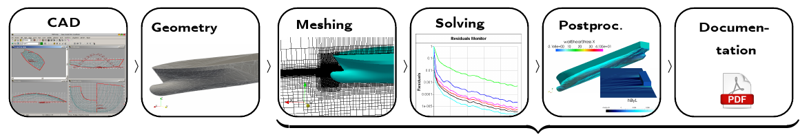
InsightCAE provides tools to automate these workflows: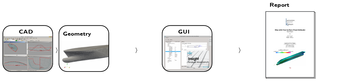
- For recurring tasks, the “best practice” approach is implemented. The user only needs to provide a few necessary parameters. A graphical user interface (GUI) allows for parameter input and contains the documentation.
Simulation Tools as Backends
We mainly use this software:

OpenFOAM is the most comprehensive free computational fluid dynamics program currently available.
It has all the functions necessary for successful CFD application. In addition, the source code is completely open, and it is completely free. Coupled with good parallel scalability, this opens up great potential for increasing productivity and design security while reducing costs.
The focus of OpenFOAM is on Computational Fluid Dynamics. However, due to its open and modular architecture, the software is also ideal for solving other tasks, such as calculating electric and magnetic fields. Particularly because of the boundless customization options of open-source software, highly individual solutions can be excellently developed.
Code_Aster is the finite element program from Electricite de France (EDF). Since 2001, it has been free software and is available under the GPL license.
Compared to other free FEM codes, Code_Aster stands out for its extensive functionality. In addition to the numerical solver, which operates both serially and in parallel, there is the pre- and post-processing workbench “Salome” for processing and meshing models, and for visualizing results.
Since Code_Aster is developed and used for the calculation of nuclear reactors, the code is subject to comprehensive quality control.
Code_Aster's special software architecture enables extensive automation of all calculation processes.
-
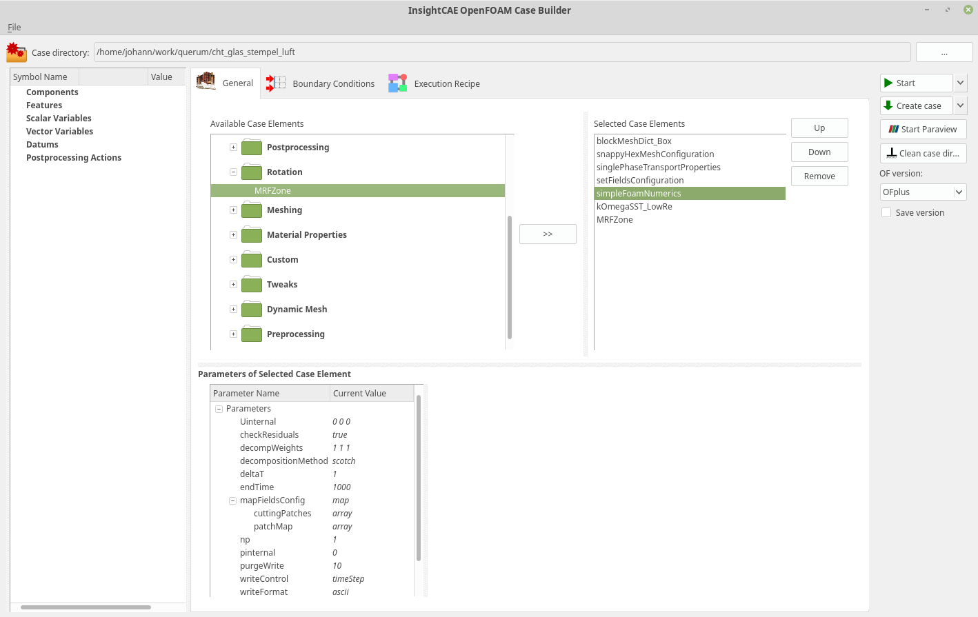
InsightCAE Case Builder for Thermal Simulations
Preparation and Case Setup for Thermal Simulation with Open Source Software such as OpenFOAM, Elmer, etc. Our software InsightCAE enables fast and automated pre- and post-processing for robust thermal spread simulation. Installation of InsightCAE software including OpenFOAM on Windows and Linux computers, implementation of software add-ons, provision of computing resources (HPC), and support ensure fast and reliable simulation results.
-

Water bodies as energy reservoirs - heat pumps, cooling water, and thermal simulation
Natural bodies of water offer enormous potential as energy reservoirs for modern heat pump systems. The targeted use of surface waters, lakes, and rivers for heat extraction and injection opens up sustainable alternatives to conventional heating solutions – but requires precise hydraulic and thermal planning to meet ecological and regulatory requirements.
Discharge of cooling water from a heat pump into a body of water
In heat pump systems that use water from bodies of water as a heat source, the cooled (in heating mode) or heated (in cooling mode) water is returned to the body of water after heat transfer. This discharge presents an engineering challenge in both winter and summer:
- Winter (Heating Mode): The heat pump extracts heat from the body of water. The returned cooling water is colder than the ambient temperature of the body of water. Local subcooling and ice formation at discharge points must be avoided.
- Summer (Cooling mode): Surplus heat is discharged into the water body. The introduced water is warmer than the natural water temperature. Thermal stratification and excessive warming of sensitive shallow water zones are critical to evaluate.
Official limits for temperature changes in bodies of water (typically ±3 K compared to the natural temperature in Germany) must be strictly adhered to during plant design.
Thermal Simulation: Warming of Water Bodies and Water Body Beds
To realistically assess the effects of cooling water discharge, numerical thermal simulations are used. These model the spatial and temporal temperature distribution in the water body as well as in the sediment (water body bottom) and take into account the following influencing factors:
- Flow conditions Flow rate, turbulence, natural convection, and temperature stratification in the water body
- Heat conduction in sediment The waterbed stores and delays thermal influences – particularly relevant for standing bodies of water like lakes or ponds.
- Seasonal fluctuations Annual cycle of natural water temperature, winter ice cover, summer temperature stratification
- Heat Transfer at the Water Surface: Evaporation, radiation, and convective heat exchange with the atmosphere
Methods like Computational Fluid Dynamics (CFD) make it possible to identify critical areas of thermal stress early on and optimize the system accordingly.
Design of the inflow geometry
The geometry of the discharge point has a crucial impact on the speed and completeness with which the discharged cooling water mixes with the surrounding body of water. The goal is the most homogeneous mixing possible to avoid local temperature extremes. Relevant design parameters include:
- Outlet direction and angle: Introduction with water flow direction (co-current principle) promotes mixing
- Nozzle Geometry and Exit Diameter: Increasing the exit velocity improves momentum and therefore turbulent mixing
- Impedance Introduction below the thermocline or near the water bottom can utilize or bypass thermal stratification effects
- Multiple outlet distribution: Multiple smaller outlets instead of a central discharge point increase the contact area with the surrounding water
Determination of Maximum Flow Rates for Optimal Mixing
The maximum permissible flow rate of cooling water introduced is determined by the mixing behavior and compliance with temperature limits. Hydraulic mixing calculations form the basis, analyzing the ratio of the discharge flow rate to the available ambient flow rate (dilution ratio).
Key influencing factors in the design are:
- Natural flow or water volume of the water body (minimum flow MNQ for flowing waters)
- Temperature difference between the discharge and the water body (ΔT)
- Thermal output of the heat pump and COP (Coefficient of Performance)
- Administrative requirements from water law (Water Resources Act, state water laws)
Based on these parameters, the maximum flow rate can be iteratively determined, ensuring compliant and environmentally sound discharge.
Conclusion: Bodies of Water as a Sustainable Heat Source
The use of bodies of water as energy reservoirs for heat pump systems is a technically mature and climate-friendly solution – provided that planning, simulation, and design are carried out carefully and in accordance with regulations. Thermal simulation combined with optimized inflow geometry and well-founded flow rate measurement ensures that neither ecology nor efficiency are compromised.
Planning a project involving water-based heat utilization? We support you with thermal simulations and hydraulic calculations.
-

CFD Simulation of Airbag Gas Generators – Compressible Flows and Shock Waves
The gas generator is the safety-critical core of every airbag system. Within a few milliseconds, it must provide a defined amount of gas with precisely controlled pressure and temperature – reliably, reproducibly, and under extreme conditions. The fluid dynamics processes that occur – compression shocks, expansion waves, heat transfer, and real gas behavior – are highly dynamic and difficult to fully capture with measurement technology. Computational fluid dynamics (CFD) is therefore an indispensable tool in the development and design of modern gas generators.
Simulation of compressible flows in the gas generator
Unlike incompressible flows – such as in classical hydraulic systems – all essential effects of compressible gas dynamics taken into account. Our CFD simulations fully represent these physical phenomena:
- Shock waves – abrupt, discontinuous changes in the flow field with a sudden increase in pressure, density, and temperature; significant for pressure peaks and structural loads in the housing
- Expansion waves Prandtl-Meyer expansion at geometric transitions and nozzle sections, relevant for flow guidance and momentum distribution in the gas stream
- Compression and Expansion – Influence on temperature and pressure development during the transient filling process of the airbag cushion
- Supersonic flows and Mach number distribution – Design of nozzles and outlets for defined flow regimes
Stationary and Transient Simulation – Methodology and Tools
Depending on the question, we use stationary simulations for basic design and parameter studies, or fully transient calculations to map the highly dynamic ignition and filling process. Our simulation workflows are based on proven open-source and commercial CFD solvers and are managed via our software environment InsightCAE efficiently controlled
- Density-based solvers for compressible high-speed flows with shock capturing
- Adaptive Time Stepping for Stable Transient Simulations with CFL Criterion
- Network refinement in shock zones and near-wall regions for precise gradient resolution
- Parametrized model constructions for efficient variant studies of geometry, pressure, and gas specification
Application areas and development goals
CFD simulation of airbag gas generators supports all phases of product development – from conceptual design to virtual validation before crash testing:
- Design and optimization of nozzle and outlet geometries for defined filling behavior
- Evaluation of different generator concepts – pyrotechnic, hybrid, or cold gas – with regard to pressure-time profile and gas temperature
- Thermal protection of airbag fabric by limiting gas outlet temperature
- Functional proof at extreme temperatures according to automotive standards (e.g., -40°C to +85°C ambient temperature)
- Reduction of development costs and testing effort through virtual variant assessment before physical prototyping
Request CFD simulation for your gas generator
Are you developing or optimizing a gas generator for airbag systems or related pyrotechnic or pneumatic applications? Speak to us - we develop a precise simulation model with you that accelerates and secures your development process.
-
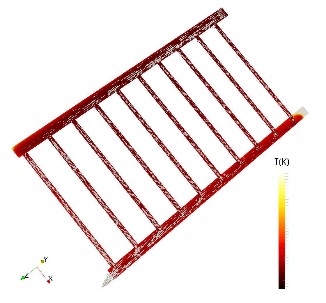
CFD Simulation of Solar Collectors – Thermal Design and Flow Optimization
The efficiency of a solar collector depends on a variety of interacting physical influencing factors – solar radiation, ambient temperature, wind speed, collector geometry, flow guidance, and heat transfer to the carrier medium. A purely experimental design is costly and time-consuming, providing only isolated insights. Numerical fluid dynamics and heat transfer simulation (CFD), on the other hand, enables a complete, spatially resolved analysis of thermal and fluid mechanical behavior – for any operating conditions and collector configurations.
Thermal Simulation: Warm-up Under Real Operating Conditions
We determine the heating of the heat transfer fluid in solar collectors, taking into account all relevant environmental influences – steady-state for design operating points as well as transient for mapping daily and seasonal fluctuations:
- Solar irradiance – Variation of global solar radiation from cloudy conditions to maximum direct radiation; consideration of the angle of incidence depending on collector tilt, geographical location, and time of day
- Outside temperature – Influence of ambient temperature on heat losses through the cover glass, frame, and back of the collector; simulation of seasonal operating points from winter to midsummer
- Wind speed and direction – convective heat losses on the collector surface due to airflow; identification of critical wind exposure areas and aerodynamic pressure distributions
- Heat loss analysis – Quantification of losses due to convection, radiation, and heat conduction to determine thermal efficiency
Flow Engineering: Flow Rates and Pressure Losses
Besides thermal performance, the hydraulic design of the collector is crucial for system efficiency and operational reliability. Uneven flow through the absorber channels leads to local overheating, increased wear, and reduced heat yield. We simulate and optimize:
- Flow rate distribution – Uniform flow through all absorber pipes or channels as a basic prerequisite for maximum thermal efficiency; Identification and remediation of flow imbalances
- Pressure drop calculation – Determination of the total pressure loss across the collector as the basis for the design of the circulation pump and the piping system
- Channel Geometry and Absorber Design – Comparison of different fin geometries (harp fins, meander fins, plate absorbers) with regard to pressure drop and heat transfer efficiency
- Influence of the heat transfer medium – Water, water-glycol mixtures, or special fluids with temperature-dependent material properties
Collector types and areas of application
Our simulation methods are applicable to all common solar collector technologies.
- Flat-plate collectors – the most widespread collector type for hot water heating and heating support; simulation of the glass cover, absorber plate, and insulation layer
- Vacuum tube collectors - Higher efficiency with diffuse radiation and low outside temperatures; flow and heat simulation in the annulus and heat pipe
- Concentrating Collectors (CPV/CSP) – Parabolic troughs, Fresnel collectors, and dish systems for process heat and solar thermal power plants
- Air collectors – direct heating of air as a heat transfer medium for drying systems, building ventilation, or agricultural applications
Solar collector simulation request
Are you developing a new collector, optimizing an existing design, or planning a collector field for an industrial or building application? Speak to us – we support you with precise CFD simulation from the initial concept to series production design.
-
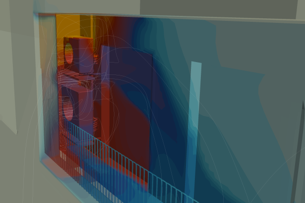
Building Climate Control – Simulation of Temperature Distribution and Air Circulation
Numerical simulation of temperature distribution and climate control enables precise, data-driven planning of rooms and halls – even before the first groundbreaking or the next renovation. With the help of modern CFD (Computational Fluid Dynamics) methods, thermal weak points can be identified early and remedied effectively.
What can thermal building simulation achieve?
Our simulation solutions cover the entire spectrum of thermal and fluid flow analysis:
- Visualization of thermal bridges Critical areas in facades, roofs, and connections become visible before they lead to structural damage or energy loss.
- Overheating analysis – Taking wind direction, solar radiation, and seasonal climate data into account, the thermal behavior of buildings is realistically calculated.
- Energy optimization of room ventilation Targeted adjustment of air supply and exhaust systems to ensure healthy indoor air and efficient energy use.
- Hall ventilation and industrial ventilation Especially in large production and warehouse halls, well-thought-out air flow is crucial for occupational safety and system performance.
InsightCAE Add-On for Building Ventilation Simulation
The specially developed InsightCAE Add-On for Building Ventilation Simulation offers a powerful and user-friendly environment for the complete simulation chain – from geometry to results.
- Interactive Geometry Creation from existing 2D plans or BIM data (Building Information Modeling) - without complex manual modeling.
- Seamless integration into existing planning and engineering workflows.
- Developed in close collaboration with a major industrial client - practical, tested, and aligned with real-world requirements.
Why numerical simulation instead of traditional planning?
Conventional calculation methods quickly reach their limits with complex building geometries, variable climatic conditions, or industrial requirements. Numerical flow and thermal simulation, on the other hand, provides:
- Spatially resolved temperature and flow fields in 3D
- Quantitative Evaluation of Different Ventilation Concepts in Direct Comparison
- Understandable, documentable results for building permits, certifications, and energy performance certificates
- Early error avoidance and cost reduction through virtual optimization
Typical use cases
Thermal building simulation is used for:
- Industrial and production halls with high heat load
- Office and administrative buildings with proof of summer heat protection
- Data centers and server rooms with critical temperature requirements
- Sports venues, exhibition centers, and public buildings with large room volumes
- Building envelopes in the context of energy-efficient renovation planning
Request consultation now
Are you planning a new construction project, a renovation, or do you want to optimize the air conditioning of your existing property? Contact Us – we analyze your requirements and show you how numerical simulation saves time, costs, and energy.
-
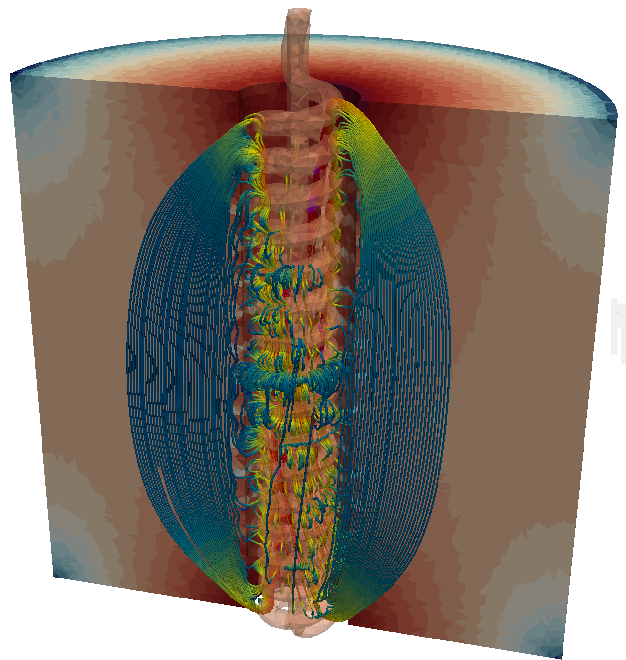
Simulation of inductive heating – Elmer and OpenFOAM
Inductive heating is an established and highly efficient process in modern manufacturing and process engineering. Whether hardening, brazing, shrinking, or targeted heat treatment – the contactless, rapid, and locally precise heat input makes induction heating the method of choice in numerous industries. However, the underlying physical interactions between the electromagnetic field, induced current, and resulting heat distribution are complex and difficult to predict without numerical simulation.
We simulate inductive heating processes for technical components made from various materials – in 2D and 3D, including surrounding media. We combine electromagnetic field simulation with Elmer and the heat transfer calculation with OpenFOAM to a powerful, coupled multiphysics simulation – integrated into our software environment InsightCAE.
What does inductive heating simulation achieve?
Numerical simulation of induction heating allows for a complete, physically consistent description of the heating process – from coil geometry to the temperature distribution in the component and its surroundings:
- Calculation of the electromagnetic field distribution – Magnetic field strength, current density, and eddy current losses as a function of frequency, coil geometry, and material parameters
- Spatial distribution of heat sources local heat input derived from Joule losses as the basis for thermal analysis
- Stationary and transient heat propagation – Temperature trends over time and space, cooling behavior, thermal gradients, and hot spots
- Environmental influence – Heat conduction into adjacent components, radiation, and convection at surfaces are fully accounted for
- Material Nonlinearities – temperature-dependent electrical conductivity, heat capacity, and thermal conductivity are correctly represented
Coupled Multiphysics Simulation: Elmer + OpenFOAM in InsightCAE
The physical peculiarity of inductive heating lies in the close coupling of electromagnetics and heat transport. Both domains influence each other: the electromagnetic field determines the heat sources, while the temperature changes the material-dependent electromagnetic properties. This bidirectional coupling requires specialized simulation tools.
- Elmer (FEM) resolves the Maxwell equations for electromagnetic field simulation, calculates eddy currents and Joule loss power in the component and its surroundings
- OpenFOAM (FVM) – handles the heat transfer calculation, maps stationary and transient temperature fields, and considers conduction, convection, and radiation
- InsightCAE – our own simulation environment coordinates the data exchange between both solvers, manages the coupling steps, and provides an end-to-end workflow environment from geometry preparation to result evaluation
2D and 3D Simulations – Materials and Geometries
Depending on the complexity of the task, we use rotationally symmetric 2D models for rapid parameter studies or complete 3D models for geometrically complex components and asymmetric coil arrangements. Components made of:
- Steels and special steels – ferromagnetic and austenitic, with and without phase transformation
- Aluminum and copper alloys – high electrical conductivity, low skin effect at high frequencies
- Titanium-based alloys - relevant for aerospace and medical technology
- Composite materials and multilayer systems – e.g., coated components or cast-in inserts
Typical applications of induction heating simulation
The simulation of inductive heating processes is crucial in a wide variety of processes and industries:
- Induction hardening – Prediction of hardening depth, temperature profiles, and quenching behavior for gears, shafts, and bearing rings
- Induction soldering and welding Optimization of heat input for reproducible bonded joints
- Shrink fits – Thermally controlled expansion of hubs and rings for mounting press fits
- Preheating before forming – Forging, cold forming, or hot bending with targeted local preheating
- Plastics processing and composite materials – inductive heating of inserts or tools
- Test and Measurement Technology – non-destructive testing using eddy current testing
Advantages of numerical simulation over purely experimental approaches
- Visualization of internal temperature fields that are not accessible or only accessible with great effort through measurement.
- Systematic variation of coil geometry, frequency, power, and component position without physical prototypes
- Early identification of overheating zones, insufficient penetration depth, or uneven heating
- Reduction of development times and reduction of scrap and rework in series production
- Securing and Documenting Process Parameters for Quality Management and Certifications
Request induction heating simulation now
Do you want to optimize an induction heating process, design a new procedure, or test an existing component for thermal load capacity? Speak to us - We analyze your task and develop a customized simulation model using Elmer, OpenFOAM, and InsightCAE.