Month: April 2026

  • Gekoppelter Wärmetransport – Conjugate Heat Transfer

    Coupled Heat Transfer – Conjugate Heat Transfer

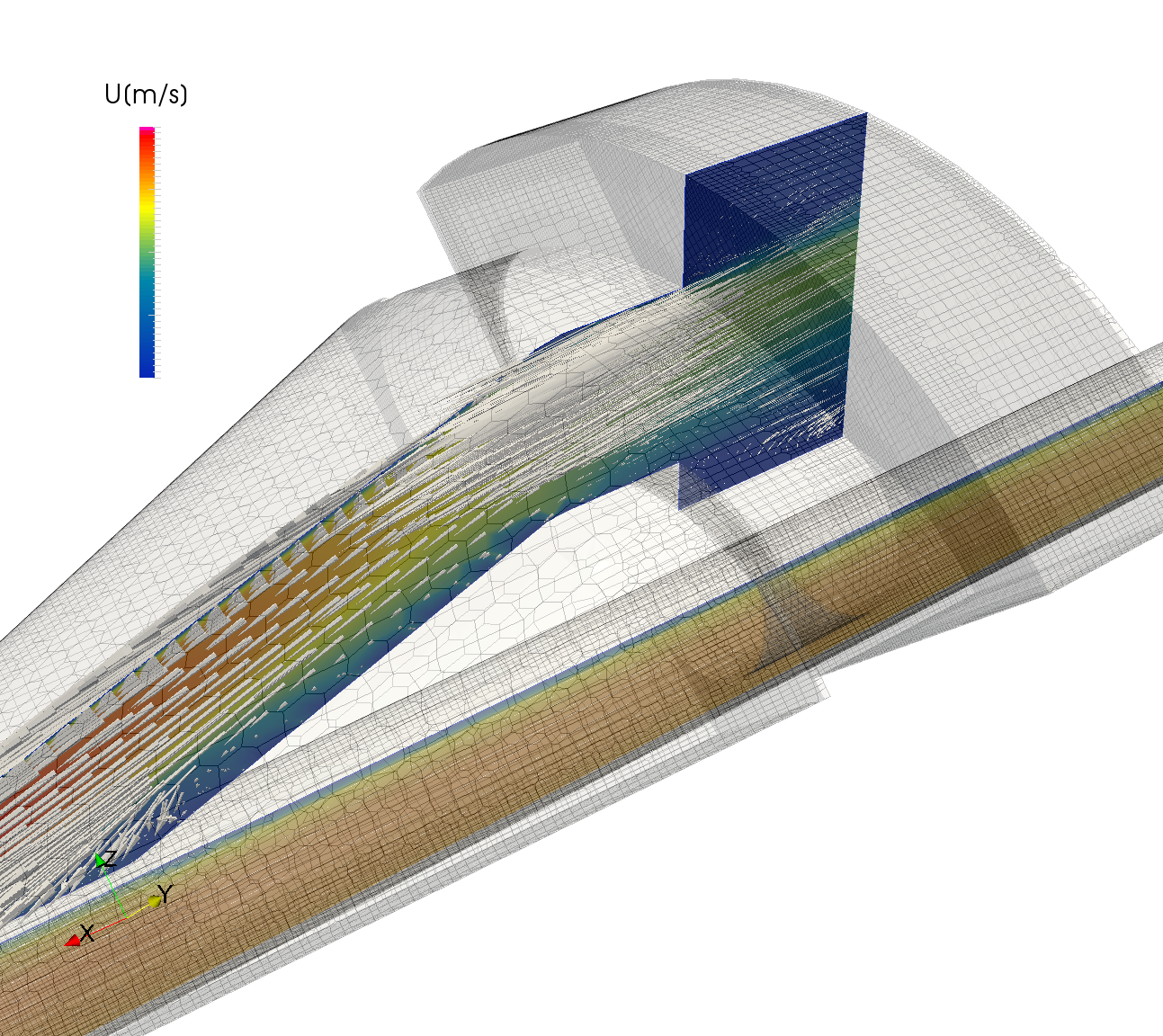
    In some simulation problems, not only the heat transfer within the fluid plays a role, but also that in the adjacent solid. In such cases, a coupled simulation of heat propagation between the solid and fluid (CHT – Conjugate Heat Transfer) must be performed.

    We master such simulations with our open-source tools, e.g. OpenFOAM. For rapid optimization of heating and cooling performance using numerical simulation, we have created additional tools to accelerate the preparation of such simulations.

  • Wärmetransport

    Heat transfer

    Stationary and transient 3D simulation of heat propagation in complex components made of different materials. Cooling and heating of components to determine critical heat flows, required cooling loads or e.g. avoidance of thermal stresses. Optimization of component geometries through automated geometry creation and simulation processes.

  • Ausbreitung von Gasen in der Umwelt

    Dispersion of gases in the environment

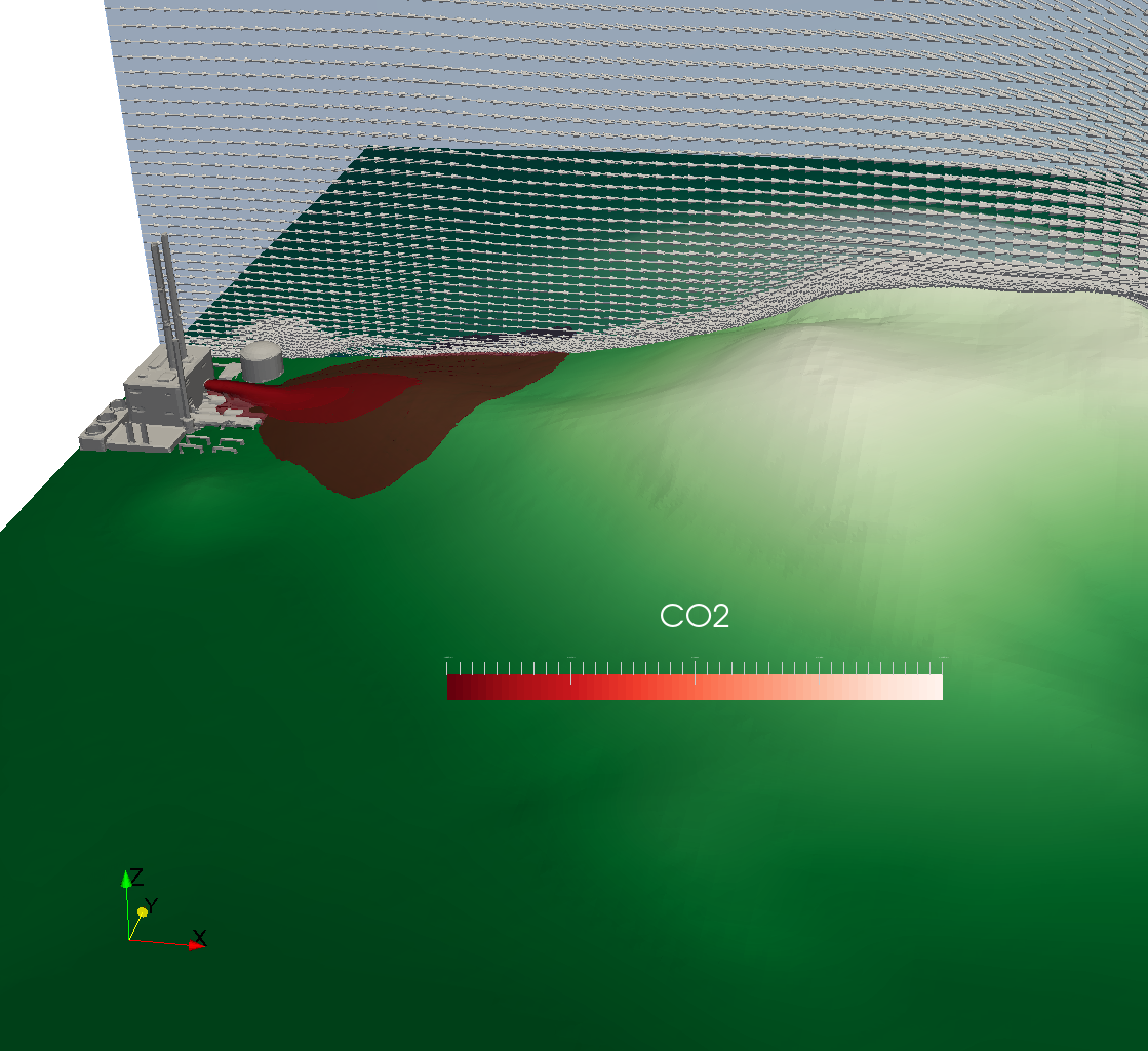
    CFD simulation of gas dispersion in accident scenarios – Safety analysis for light and heavy gases

    For industrial plants, chemical facilities, energy supply infrastructures, and safety-critical installations, the uncontrolled release of gases in the event of a malfunction poses a significant risk to people, the environment, and assets. The precise prediction of gas dispersion is therefore an essential component of modern safety analyses, risk assessments, and emergency planning.

    Simulation-based Accident Analysis with CFD

    Using CFD (Computational Fluid Dynamics) simulations, escaping gases in fault scenarios – both light gases (e.g., hydrogen, methane, ammonia) and heavy gases (e.g., chlorine, propane, CO₂) – are precisely captured in their spatial and temporal dispersion. The simulation takes into account the immediate surroundings (building contours, obstacles, terrain structure) as well as the distant surroundings (building density, topography, open areas) to model realistic dispersion scenarios.

    Stationary and transient concentration fields

    The calculation of both steady-state and transient concentration fields allows for a differentiated assessment of the dispersion dynamics:

    • Stationary fields show the steady state under a constant leakage rate and provide information about permanently critical zones, explosion limits (LEL/UEL), and toxicity thresholds (e.g., ERPG, AEGL, or IDLH values).
    • Transient fields depict the temporal course of the spread – from release through cloud formation to dilution – and are crucial for assessing evacuation periods and alarm concepts.

    Influence of different wind directions and meteorological conditions

    Wind direction, wind speed, and atmospheric stability classes (according to Pasquill-Gifford or Monin-Obukhov) have a significant influence on the range, concentration, and hazard zone of a gas cloud. By systematically varying these parameters, all safety-relevant scenarios are covered – from calm weather conditions with low mixing to turbulent flow with rapid dilution.

    Transient Inflow Boundary Conditions in Atmospheric Boundary Layers

    An essential quality feature of the simulation is the use of custom-developed transient inflow boundary conditions for atmospheric boundary layers. In contrast to simplified wind profiles, realistic, time-varying flow profiles with turbulent boundary layer structure are used. This ensures a high degree of agreement with real meteorological conditions and significantly increases the reliability and validity of the simulation results – a crucial advantage over classic Gaussian dispersion models.

    Application areas and regulatory framework

    CFD-based gas dispersion simulation is used in:

    • Accident Prevention Ordinance (12. BImSchV) / Seveso III Directive: Proof of safe distances and safety zones
    • Safety reports and QRA (Quantitative Risk Assessment): Basis for probabilistic risk assessments
    • Fire and disaster control planning: Support for deployment scenarios and evacuation planning
    • Facility Planning and Approval Procedures Early identification of critical spread pathways

  • Kühlung elektronischer Bauteile

    Cooling of electronic components

    Thermal Simulation and Thermal Management in Electronics and Lighting Development

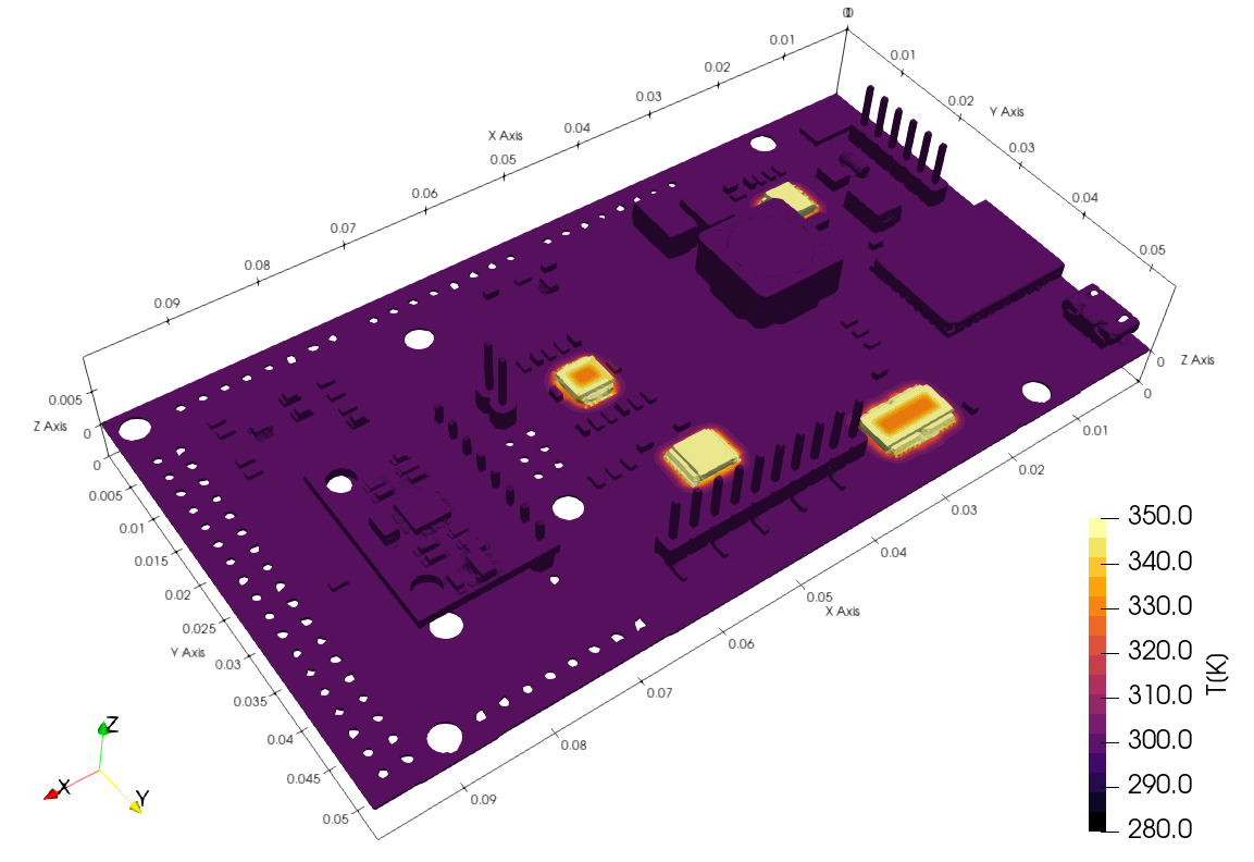
    In modern development processes, thermal management is a central challenge – especially for high-performance components such as electronic assemblies, power electronics, and LED light sources. Using 3D CFD (Computational Fluid Dynamics) simulations and FEM (Finite Element Method)-based thermal analysis, precise thermal analysis is performed for the cooling of various components, including electronics, light sources, and embedded systems.

    Heat transfer mechanisms in detail

    A realistic simulation considers all relevant heat transfer mechanisms:

    • Heat conduction (conduction): The quantification of heat conduction through solid materials such as printed circuit boards (PCBs), heat sinks, and housing materials enables the targeted selection of thermally optimized materials and material composites.
    • Thermal radiation Calculating emitted infrared radiation based on emissivity and surface temperatures is particularly relevant at high operating temperatures and in a vacuum.
    • Free convection (natural convection): Without active cooling elements, air circulation is created solely by density differences in the heated fluid – ideal for silent, low-maintenance designs.
    • Forced convection Fans, blowers, or pumps generate a defined flow of air or fluid and significantly increase heat transfer. Simulation allows for the optimization of flow guidance, duct geometry, and fan position.

    Cooling concepts and their simulation-based evaluation

    Various cooling strategies – from passive air cooling and active forced cooling to liquid cooling and heat pipes – are virtually evaluated before a physical prototype is created. Key performance indicators such as maximum component temperatures, temperature gradients, thermal resistances, and compliance with limit values according to IEC, JEDEC, or UL standards are crucial evaluation criteria.

    Early Functionality Assurance in the Development Process

    By integrating thermal simulation early in the development phases – from conceptual design through detailed design to series production readiness – costly redesigns and thermally induced failures can be avoided. The simulation provides reliable statements on service life, reliability, and compliance with temperature limits (e.g., Tjunction for semiconductors or Tc values for LED modules), which are directly incorporated into the design.

    This ensures the product's functionality is reliably guaranteed during the development process – long before the first prototype.

  • Wärmeübertrager

    Heat exchanger

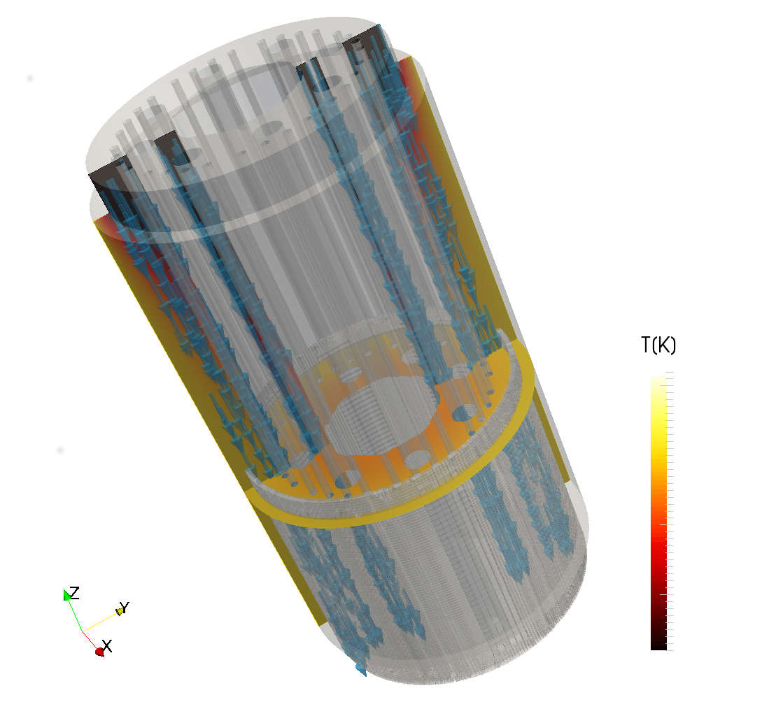
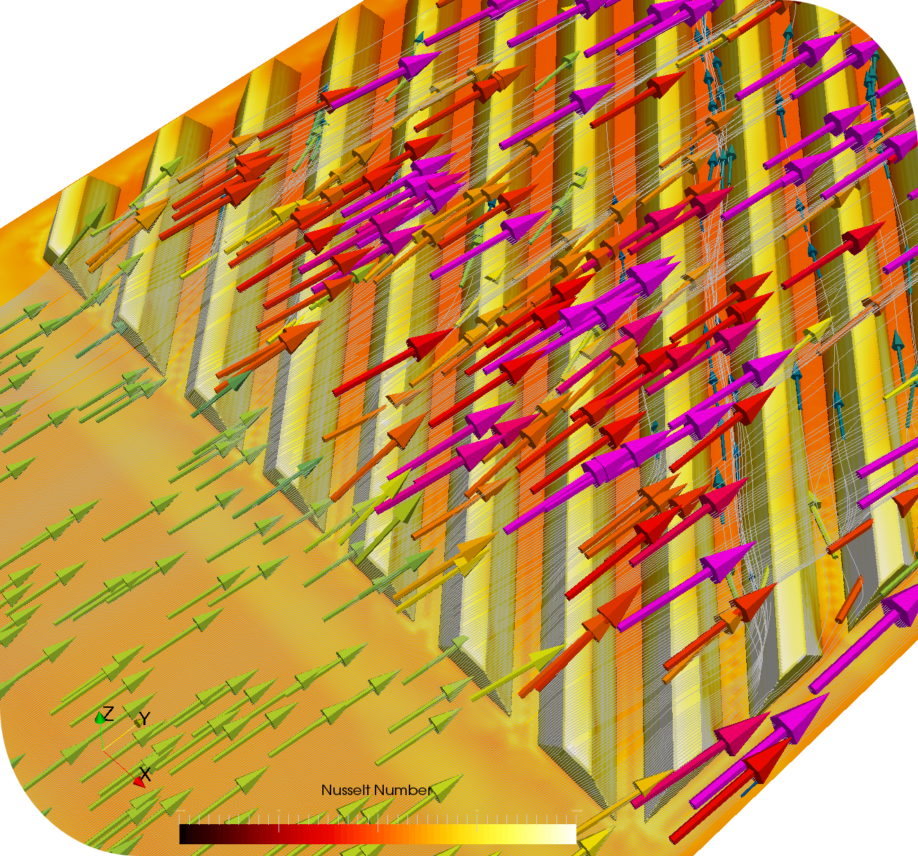
    The analysis of the flow with heat transfer at various operating points of technical components is the most important step in design and optimization. We have mastered the simulation tools required for this. Improved inflow and outflow and better flow control with minimal pressure losses reduce component and operating costs. Predictions about local thermal stresses can be derived from the 3D simulations.

  • Klimatisierung Fahrzeuginnenraum

    Vehicle interior air conditioning

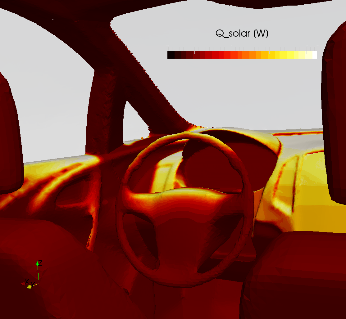
    A reduction in air conditioning energy consumption is possible through efficient and controlled ventilation. Coupled simulations (thermal radiation, conduction, convection) calculate temperatures within the vehicle and on its surfaces due to solar radiation. Optimized software (InsightCAE) for solving transient thermal radiation using CFD, taking into account thermal capacities, enables fast and efficient simulations for the client.

  • See

    See

    Thermal flow simulation for spatial energy planning with seawater

    Lakes and other surface waters represent an enormous natural energy reserve that can be utilized both ecologically and economically efficiently. By using lake water heat pumps, this stored thermal energy can be harnessed for the heating and cooling supply of buildings, thereby contributing significantly to the decarbonization of municipal heat supply. Thermal flow simulations form an indispensable basis for spatial energy planning and enable a well-founded assessment of the framework conditions and requirements for sustainable thermal utilization of lake water.

    Flow simulation as a planning tool for authorities, planners, and energy suppliers

    A significant advantage of thermal flow simulations lies in their communicative function: they make the expected thermal and fluid mechanical conditions in bodies of water clearly and understandably visible to all stakeholders – authorities, planners, and energy suppliers. This considerably simplifies water law approval processes and creates a shared planning basis on which well-founded decisions can be made regarding locations, performance classes, and operating concepts for the use of lake water.

    3D modeling through depth map digitization

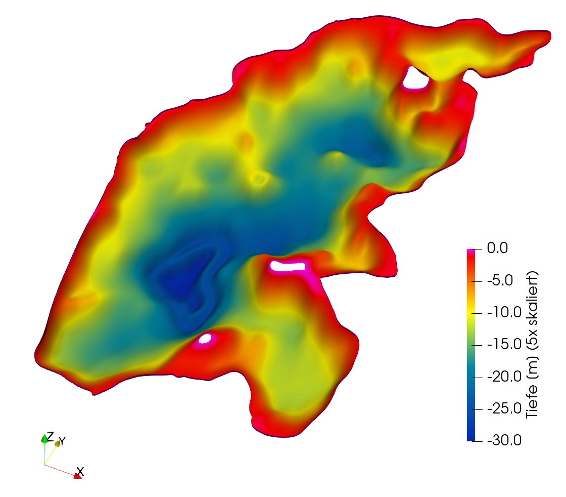
    The basis of any thermal flow simulation is a precise digital terrain model of the water body. For this purpose, existing depth maps are digitized and transferred into a three-dimensional computational model that accurately depicts the real basin geometry with its depths and shorelines. The more accurately this 3D model reflects the actual bathymetric conditions, the more reliable and meaningful the results of the CFD simulation will be.

    Simulation of temperature stratification in heating and cooling operation

    The flow simulation realistically depicts the temperature stratification in the body of water, considering both intake and discharge pipelines for heating and cooling operations. In natural waters, solar radiation, wind mixing, and seasonal influences create a characteristic thermal stratification – the so-called thermocline – which significantly influences temperature availability and flow behavior. The simulation quantifies these complex interactions between heat input/output and natural stratification, thus providing reliable planning data for the design of seawater heat pump systems.

    Temporal resolution of seasonal temperature fluctuations

    The time-resolved observation of temperature fluctuations in the body of water allows for a realistic assessment of the seasonal performance availability of the seawater system over a complete annual cycle. Temperature profiles and their dependence on weather influences, usage intensity, and operating regimes can thus be analyzed in detail and used for system design.

    Optimization of the supply and return geometry to avoid short-circuit flows

    By systematically varying the supply and return geometries—that is, the number, arrangement, and orientation of the intake and outfall structures—the respective thermal influence zones in the water body are determined. In this way, hydraulic and thermal short-circuit flows can be reliably avoided, the efficiency of seawater utilization can be maximized, and potential ecological impacts on the water body can be reduced to a minimum.

  • Hafenbecken

    Harbor basin

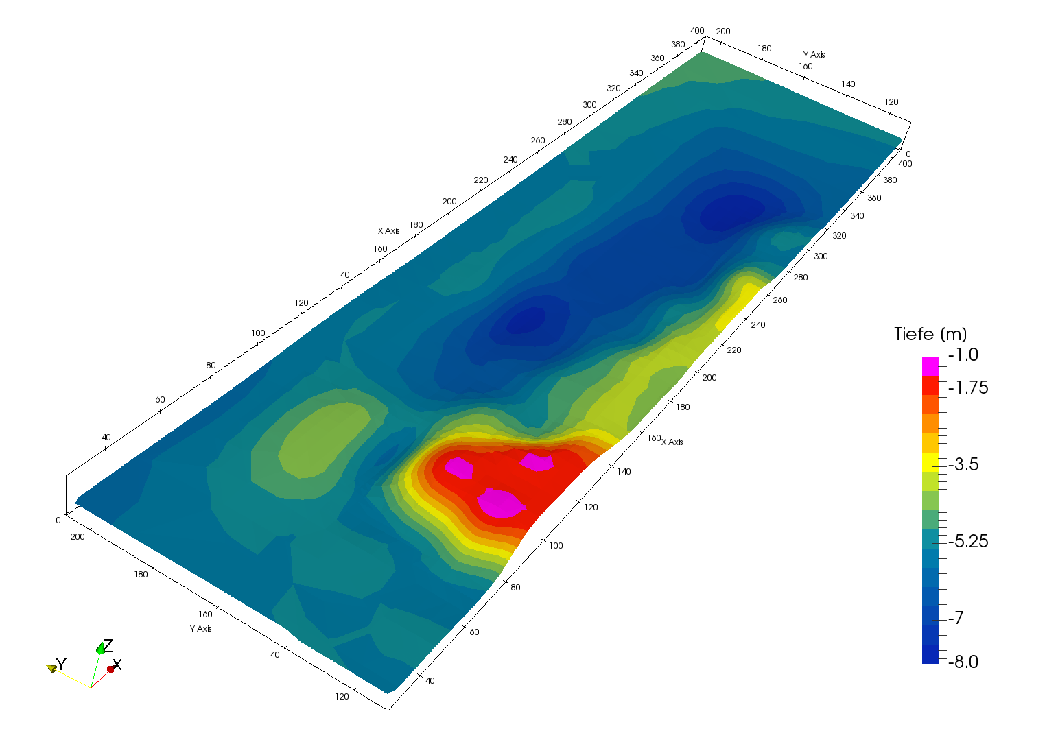
    As part of an innovative energy concept, a harbor basin is being used as a natural heat source and sink for the cooling and heating operations of surrounding office buildings. Surface waters such as harbor basins, lakes, or rivers are ideally suited as the basis for water-based heat pump systems due to their thermal storage capacity and can achieve significant energy savings compared to conventional air conditioning systems.

    Thermal simulations were carried out to assess the thermal impacts on the water body, quantifying the temperature influence of heat withdrawal and heat input on the harbor basin. Such simulations are essential to ensure that the water temperature remains within ecologically and legally permissible limits and that no undesired thermal stratification occurs.

    Particular attention was paid to the hydraulic design of the supply and discharge lines at the quay wall. Thermal or hydraulic short circuits—that is, the direct return of already tempered water to the intake point—would significantly reduce the efficiency of the system. Through careful positioning and flow engineering of the inlet and outlet structures, this effect can be reliably prevented.

    To avoid excessively high flow velocities in the harbor basin, the number of inlets and outlets was varied and optimized. High local flow velocities can cause sediment resuspension, negatively impact aquatic life, and lead to increased wear on technical equipment. Distributing the volumetric flow rate across multiple discharge points reduces these risks and ensures more uniform flow through the basin.

    The intake boxes were specifically sized to prevent the entry of fish and other aquatic organisms into the pipeline system. In practice, fine-mesh grates, screens, or special protective grids are used, with flow velocities kept so low that fish are not sucked in. Corresponding limit values for inflow velocity are enshrined in water law regulations and environmental requirements.

    Finally, the biological compatibility of the entire system was investigated. Possible impacts on the harbor basin ecosystem were assessed, particularly with regard to temperature changes, altered oxygen levels, and the introduction of non-native organisms. Environmentally compatible planning ensures that the operation of the facility is in accordance with water law approval requirements and the objectives of the European Water Framework Directive.

  • FEM-Simulation von Klebeverbindungen – Präzise Spannungsanalyse für sichere Fügetechnik

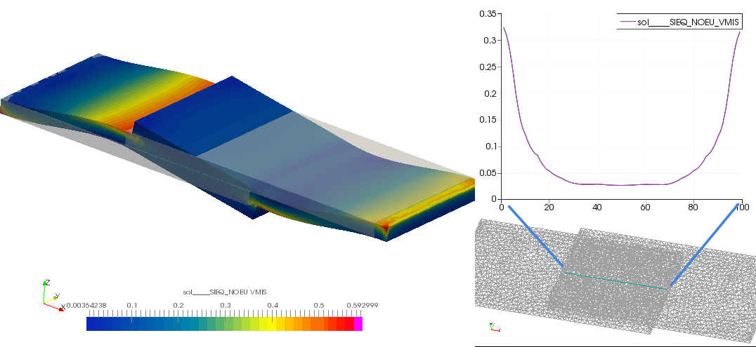
    FEA Simulation of Adhesive Bonds – Precise Stress Analysis for Secure Joining Technology

    Adhesive bonding is playing an increasingly important role in modern constructions – from aerospace and automotive engineering to wind turbines and general mechanical engineering. In contrast to form-fitting connections such as screws or rivets, adhesive bonds transmit loads over an area, reduce notch effects, and enable the joining of diverse materials. This makes reliable computational assessment all the more important – especially with the Finite Element Method (FEM).

    FE Modeling of Adhesive Joints

    Similar to bolted connections, adhesive bonds can also be precisely considered in FEM models. We use a modeling technique that not only correctly maps global load transfer but also enables a sufficiently detailed assessment of stresses within the adhesive layer itself. This reliably identifies and evaluates critical areas such as adhesive layer edges, overlap zones, and peel stress peaks.

    Why is correct FEM modeling of adhesive layers crucial?

    The adhesive layer is the mechanically critical element of the bond, despite its often small thickness. Simplified or neglected modeling frequently leads to:

    • Underestimation of peeling stresses at the edges of the overlap – one of the most common failure mechanisms for adhesive bonds
    • Faulty stiffness mapping of the overall system, especially with hybrid constructions made of metal and fiber composite materials
    • Inadequate assessment of fatigue loads, which can lead to creeping failure of the interface under cyclic loading
    • Overlooking residual stresses from the curing process, which significantly affects the effective load-bearing capacity

    Our modeling strategy in detail

    Depending on the requirements and available computing power, we use different, coordinated modeling approaches:

    • Volume elements for the adhesive layer enable direct, three-dimensional stress evaluation within the adhesive, particularly for normal and shear stress components
    • Cohesive Zone Models (CZM) represent the progressive failure of the interface and are suitable for fracture mechanics and delamination analyses
    • Tie-constraints and surface-to-surface contacts – for efficient modeling in system simulations with many joining partners
    • Material Models for Adhesives – from linear-elastic through viscoelastic to elastoplastic, adapted to the respective adhesive type (epoxy resin, polyurethane, acrylate, etc.)

    Evaluation criteria and proof of failure

    Based on the FEM results, we perform a structural mechanics assessment according to recognized codes and internal methods:

    • Stress-based detection of shear, peel, and normal stresses in the adhesive layer
    • Comparison with adhesive properties from data sheets or own tests (e.g., tensile shear test according to DIN EN 1465)
    • Safety evidence against cohesive and adhesive failure
    • Consideration of temperature influences on adhesive properties (glass transition temperature, thermal expansion)

    Typical application areas

    Our FEM-based adhesive joint analysis is used in many industries and components:

    • Structural Adhesions in Lightweight Construction – Aluminum-CFRP Hybrid Joints, Sandwich Structures
    • Wind turbines – Rotor blade bonding and flange connections
    • Automotive engineering – body stiffeners, windshield bonding, battery enclosures
    • Mechanical and apparatus engineering – Adhesive bonding for bearings and seals under mechanical and thermal loads
    • Electronics and Medical Technology – Miniaturized Adhesive Bonds with High Reliability Requirements

    Simulate adhesive bond now

    Do you want to computationally verify the load-bearing capacity of an adhesive bond or expand an existing FEM model with a realistic adhesive layer modeling? Contact us.

  • FEM-Simulation mit Code_Aster – Über 10 Jahre Erfahrung in der Strukturanalyse

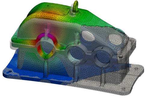
    FEM Simulation with Code_Aster – Over 10 Years of Experience in Structural Analysis

    Code_Aster is one of the most powerful yet demanding open-source finite element codes worldwide, developed and continuously maintained by the French energy company EDF. With a feature set that surpasses many commercial FEM programs, Code_Aster is particularly well-suited for complex structural, thermal, and coupled analyses in industrial and scientific environments.

    We have more than 10 years of practical experience in the professional use of Code_Aster and use this FEM code for a wide spectrum of demanding calculation tasks – from simple static analysis to highly complex transient simulations with nonlinear material behavior and contact.

    Our services with Code_Aster at a glance

    Static and transient structural analyses

    Whether it's operating load, impact, or time-varying loads – we calculate the mechanical behavior of components and structures under realistic load conditions. We utilize the full range of element types offered by Code_Aster:

    • Volume elements – for massive components, welds, and complex 3D geometries with detailed stress analysis
    • Shell elements – for thin-walled structures like sheet metal, containers, pipelines, and housings with high computational efficiency
    • Stab and beam elements – for frame structures, steel structures, and system models with many degrees of freedom

    Contact problems and nonlinear analyses

    Contact problems are among the numerically most challenging tasks in FEM. Code_Aster offers robust algorithms for this purpose, which we specifically employ for issues such as press fits, bonded joints, sealing surfaces, or the lifting of components under operational loads. Geometric and physical nonlinearities – such as large deformations or elastoplastic material behavior – are also accurately represented.

    Screwed connections

    The realistic modeling of bolted connections in FEM models requires both methodological know-how and experience with the peculiarities of the respective solver. We simulate pretension forces and the elastic behavior of bolted connections using proven methods – for reliable validations according to common standards such as VDI 2230.

    Eigenfrequency analysis and modal analysis

    Knowledge of the natural frequencies and mode shapes of a structure is a prerequisite for assessing resonance risks and designing vibration-damped constructions. With Code_Aster, we perform modal analyses and, if necessary, combine them with harmonic or transient vibration response calculations – for example, for rotating machinery, piping systems, or seismically stressed installations.

    Why Code_Aster – and why with us?

    • No licensing cost overhead Code_Aster is open source under the GPL license and enables cost-effective calculations even with high computational volumes or parallel projects.
    • High solver quality The code has been used and validated by EDF for safety-critical applications in nuclear engineering and power supply for over 30 years.
    • Reproducible, documented results – all simulations are built in a traceable manner and completed with engineering evaluation of the results

    Typical Industries and Application Areas

    Our Code_Aster projects span numerous industrial and engineering fields:

    • Mechanical and plant engineering – stress analysis for pressure vessels, flanges, welded constructions
    • Energy and Process Engineering – Piping Analyses, Heat Exchangers, Vessel Design
    • Vehicle and Rail Vehicle Technology – Crash-Relevant Structures, Durability Proofs
    • Aerospace – Lightweight structures with fiber composite materials and adhesive bonding
    • Construction and Infrastructure – Seismic Analysis, Steel Construction, Foundation Verification

    Requesting FEM calculation with Code_Aster

    Are you looking for an experienced partner for structural mechanics calculations with Code_Aster? Contact us – we will discuss your task and jointly develop an efficient and robust simulation strategy.