Category: Turbomachinery and Propellers

  • CFD-Analyse und Entwurf von Turbomaschinen mit Open-Source-Software

    CFD Analysis and Design of Turbomachinery with Open-Source Software

    Turbomachinery – from centrifugal pumps and compressors to turbines and fans – is the backbone of modern industrial and energy facilities. Their design and optimization require a deep understanding of fluid mechanics and precise numerical tools. We combine both: sound engineering expertise with state-of-the-art CFD technology based on completely free software.

    Performance Analysis and Design of Turbomachinery with CFD

    We are conducting basic Performance analyses and designs of turbomachinery through with state-of-the-art CFD (Computational Fluid Dynamics) methods. The entire analysis workflow is in InsightCAE-Framework fully automated and exclusively uses open-source software. This enables very cost-effective simulations, short turnaround times, and easy integration into automated optimization frameworks.

    What are turbomachines – and why is CFD so crucial?

    Turbomachinery are rotating fluid machines that transfer energy between a fluid and a rotor. They can be broadly divided into two categories:

    • Machinery (e.g., pumps, compressors, blowers): transfer mechanical energy to the fluid
    • Power machines (e.g., turbines, water turbines): extract energy from the fluid and convert it into rotational work

    The internal flow processes—secondary flows, separations, shock-boundary layer interactions, gap flows—are complex and analytically difficult to fully grasp in detail. Therefore, Computational Fluid Dynamics (CFD) is today the standard tool for the design, analysis, and optimization of these machines.

    Our CFD Workflow for Turbomachinery in Detail

    Our analysis process covers the entire workflow of a turbomachine simulation – from geometry preparation to result evaluation:

    • Geometry Creation and ParameterizationDefinition of blade and housing geometry, optionally based on existing CAD data or through parametric new design
    • Networking (Meshing)Automated generation of structured or unstructured computational grids with optimized wall resolution (y⁺ control) for accurate boundary layer modeling
    • Steady-state and transient simulationCalculation of operating points using RANS turbulence models; unsteady rotor-stator interactions as needed
    • Performance curvesDetermination of free-running curves, pressure-flow rate characteristics, efficiencies, cavitation limits, and other machine-specific parameters
    • Results Evaluation and VisualizationAutomated post-processing pipelines deliver reproducible, comparable reports

    InsightCAE: Fully Automated CFD Workflow Based on Open Source

    The InsightCAE-Framework is a powerful open-source automation framework for CFD and FEM analyses. It orchestrates proven open-source solvers and tools into a seamless, reproducible workflow:

    • OpenFOAM as the primary CFD solver – industrially proven, with an extensive turbulence model library
    • gmsh / snappyHexMesh for automated, quality-controlled networking
    • VTK and ParaView for scalable, script-driven visualization and analysis
    • Complete Parameterization of all workflow steps – ideal for variance calculations and sensitivity studies

    Automation eliminates manual setup effort for each individual simulation run. This not only reduces sources of error but also significantly shortens the time from problem definition to validated results.

    Seamless integration into optimization frameworks

    A particular advantage of the automated workflow is the easy connection with numerical optimization methods. Typical use cases include:

    • Gradient-based optimization for targeted improvement of efficiency or pressure buildup
    • Evolutionary Algorithms and Surrogate Models (e.g., Gaussian Process Regression) for the exploration of large parameter spaces
    • Multi-objective optimization (e.g., simultaneous maximization of efficiency and operating range)
    • Design of Experiments (DoE) for the systematic investigation of geometric or operational influencing factors

    Since each simulation run is fully script-driven and parameter-controlled, hundreds of variants can be calculated and evaluated without manual intervention.

    Benefits of our approach at a glance

    • Cost-effectiveNo license costs for commercial CFD software
    • FastAutomated workflow minimizes manual interventions and turnaround times
    • ReproducibleFully documented, versionable simulation setups
    • ScalableFrom individual simulation to automated optimization campaign
    • TransparentOpen-source software means full traceability of all calculation steps

    Typical fields of application

    Our CFD analyses for turbomachinery are used in a variety of industrial and research projects:

    • Vortex pumps and pump turbines (also for hydropower and pumped storage)
    • Axial and radial compressors for process and energy technology
    • Ship propellers and jet propellers (in combination with our drag analysis)
    • Fans and blowers for air conditioning and ventilation technology
    • Steam and gas turbines in power plant applications

    Conclusion: Modern turbomachinery CFD – efficient, open, optimizable

    With our fully automated CFD workflow based on InsightCAE and open-source software, we offer engineering firms, manufacturers, and research institutions powerful, cost-transparent access to professional turbomachinery simulation. From initial performance map calculation to automated shape optimization – all from a single source, reproducible, and scalable.

    Are you planning a CFD analysis for your turbomachinery? Speak to us – together we will find the right simulation strategy for your project.
  • Fluid-Struktur-Kopplung für Composite-Propeller: CFD mit OpenFOAM und Code_Aster

    Fluid-Structure Coupling for Composite Propellers: CFD with OpenFOAM and Code_Aster

    Modern fiber-reinforced composite ship and flow propellers offer significant advantages over traditional metal propellers – lower weight, improved cavitation properties, and the possibility of passive pitch adjustment through targeted anisotropy. However, their flexibility presents particular design challenges: the aerodynamic or hydrodynamic performance can only be correctly assessed if the structural deformation under operational load is included in the simulation.

    Composite Propellers: Opportunities and Design Challenges

    Propeller with wings made of Fiber composites – especially those made of carbon fiber-reinforced plastic (CFK) or glass fiber-reinforced plastic (GFK) – are elastically deformable under operating loads. This flexibility is not a design flaw, but can be used strategically:

    • Passive pitch adjustmentThrough targeted fiber orientation, the wing twists into a more favorable airflow as the load increases – automatically, without active mechanics.
    • Cavitation reductionThe adjustment of the blade geometry under load can smooth out pressure peaks, thereby reducing the risk of cavitation.
    • Noise reductionReduced pressure pulsations through optimized load distribution over the blade
    • Weight savingsCFK propellers are significantly lighter than bronze or stainless steel propellers of the same stiffness.

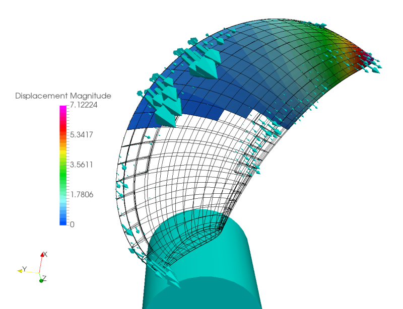
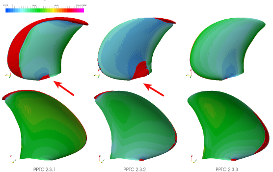
    The flip side: When interpreting, you must consider Deformation of the wings under operating load must be taken into account.. A purely rigid CFD simulation would systematically mispredict the actual geometry in operation—and thus thrust, torque, and efficiency.

    What is Fluid-Structure Interaction (FSI)?

    The Fluid-Structure Interaction (FSI) describes the interaction between a flowing fluid and an elastic structure. In the case of a composite propeller, this means:

    • The Fluid (water or air) exerts thrust on the propeller blades
    • The Structure deforms elastically as a result of these forces
    • The altered geometry in turn influences the Flow – and thus the pressure distribution
    • This cycle will iterative until convergence solved

    Depending on the stiffness of the structure and the strength of the flow forces, this coupling effect can be small and negligible—or so dominant that it fundamentally determines the design. With flexible composite propellers, the latter is usually the case.

    Our Software Solution: OpenFOAM + Code_Aster Fully Coupled

    We have a specialized Software solution for FSI simulation of composite propellers developed a solution that combines two leading open-source programs into a powerful, fully automated workflow:

    • OpenFOAM The CFD simulation handles: calculation of the flow field, pressure distribution, and hydrodynamic forces on the propeller blade – including rotating mesh regions (MRF or Sliding Mesh).
    • Code_Aster addresses the structural mechanics aspect: finite element analysis of the anisotropic composite material under the applied fluid forces, calculation of deformations and stresses in the laminate
    • An Matching algorithm transfers forces and displacements between the two solvers and updates the CFD mesh in accordance with the structural deformation (dynamic mesh morphing)

    Both tools are completely open-source – with no licensing costs, full transparency, and maximum adaptability to specific project requirements.

    Technical Features of Our FSI Solution

    • Anisotropic Material Modeling: Code_Aster models the laminate structure of CFRP and GFRP composites layer by layer—including direction-dependent stiffness and strength properties
    • Cavitation modeling: Optionally, the FSI simulation can be extended to include a cavitation model in order to capture the interaction between phase change and blade deformation
    • Automated workflow: The entire simulation workflow—meshing, solver setup, coupling, and post-processing—is script-driven and reproducible within the InsightCAE framework

    Results and key figures from the FSI simulation

    From a complete fluid-structure interaction simulation for composite propellers, you will obtain, among other things:

    • Thrust and torque characteristics considering the actual operating geometry
    • Displacement field (from which deflection, twist, torsion) over the entire propeller blade
    • Stress and Strain Distributions in Laminates – Basis for Strength Verification according to Puck, Tsai-Wu, or Similar Criteria
    • Pressure distribution on the suction and pressure sides of the wings
    • Cavitation index and cavitation propagation (with extended modeling)
    • Efficiency and operating point stability across the entire characteristic curve range

    Areas of application

    Our FSI solution for composite propellers can be used in the following areas:

    • Carbon fiber or glass fiber ship propellers for high-performance and sports boats
    • Underwater drones and AUV propulsion with noise emission or lightweight requirements
    • Wind turbine rotor blades (small wind turbines, vertical axis systems)
    • Tidal stream turbines with flexible composite blades
    • Research applications for validating FSI algorithms

    Conclusion: Precise propeller design through physically consistent FSI simulation

    Those who design composite propellers with rigid CFD risk systematic errors in performance prediction and structural design. Our coupled simulation solution, based on OpenFOAM and Code_Aster, closes this gap – cost-efficient, transparent, and fully automated. This allows you to design composite propellers as they actually work: deformed, stressed, and performance-optimized.

    Are you developing a composite propeller and need a robust FSI simulation? Contact Us We guide you from geometry to the validated result.

  • Kavitationsimulation in Turbomaschinen: CFD-Vorhersage mit OpenFOAM

    Cavitation Simulation in Turbomachinery: CFD Prediction with OpenFOAM

    Cavitation is among the most critical and costly phenomena in fluid-flow turbomachinery. It limits the operating range, reduces efficiency, causes noise and vibrations – and in the worst case, can lead to irreversible material damage within a short period. CFD-based cavitation simulation is currently the most reliable tool for effectively addressing this phenomenon even during the design phase.

    What is cavitation – and why is it so dangerous?

    Cavitation describes the local evaporation of a liquid due to a pressure drop below the vapor pressure-dependent boiling point – without a temperature increase. In turbomachinery, this pressure drop typically occurs at points of high flow velocity: on the suction side of pump impellers, at the pressure edge of propeller blades, or in tight clearance areas.

    The resulting vapor bubbles collapse abruptly as soon as they reach areas of higher pressure. This collapse creates:

    • Micro-pulse beams with local pressure peaks of several thousand bar – primary cause of material removal (cavitation erosion)
    • Pressure pulsations and vibrations, the bearings, seals, and adjacent structures are stressed
    • Learning development through broadband acoustic emissions in the characteristic crackling and knocking sound
    • Performance dropLarge cavitation areas block flow cross-sections and lead to a collapse in head or thrust.

    Cavitation as a limiting phenomenon for turbomachinery

    The Cavitation is a limiting phenomenon for turbomachinery, that operate in liquids. For predicting the onset of cavitation and its effects on machine performance, the CFD simulation as the most reliable method Einsatz. Affected are almost all machine types in which liquids are accelerated or redirected:

    • Centrifugal pumps – especially at low inlet pressure (NPSH deficiency)
    • Ship and underwater propellers – under high load or partial load operation
    • Pump turbines and water turbines (Francis, Kaplan, Pelton) – in partial load and overload ranges
    • Hydraulic Motors and Pumps in High-Pressure Systems
    • Inducer Stages in Rocket Engines and High-Performance Pumps

    Cavitation Simulation with CFD: Physical Fundamentals

    modern CFD cavitation models are based on a Two-phase approach: The flow is modeled as a mixture of liquid and vapor phases, with the local vapor fraction governed by a transport equation. Established modeling approaches include:

    • Schnerr-Sauer modelBased on the simplified Rayleigh-Plesset equation for bubble growth; well validated for pump cavitation
    • Zwart-Gerber-Belamri ModelConsiders the interaction between bubble population and mass transfer; widely used in industrial applications
    • Merkle ModelPressure-based mass transfer approach, particularly stable in transient computations

    The cavitation model is supplemented by suitable Turbulence models (k-ω SST, k-ε Realizable) and – if necessary – by models for thermal effects that become relevant with cryogenic fluids or hot water.

    What specifically does CFD cavitation simulation achieve?

    A carefully set up cavitation simulation provides much more than just a statement about whether cavitation occurs. Typical results include:

    • Cavitation InceptionDetermination of the critical operating point (pressure, flow rate, speed) at which cavitation begins – as a basis for NPSH curves and safety verification
    • Spatial cavitation propagationVisualization of steam volume fractions over blade surfaces, in the gap, or in the suction mouth – to identify areas prone to erosion
    • Performance loss due to cavitationQuantification of the head or thrust drop as a function of the cavitation index σ
    • Unsteady Cavitation DynamicsSimulation of periodically collapsing cavitation structures (cloud cavitation, sheet cavitation) and their pressure pulsations
    • Erosion potential mapsIdentification of material removal zones by evaluating local pressure pulses during bubble collapse

    Our Workflow: Cavitation Simulation with Open-Source Software

    Our cavitation simulations are fully performed with Open-source software carried out – primarily with OpenFOAM and embedded in the automated InsightCAE Workflow:

    • Geometry and networkingAutomated mesh generation with fine wall resolution and mesh refinement in cavitation-prone areas
    • Inpatient pre-examinationFast evaluation of the pressure field and identification of critical zones without a cavitation model
    • Unsteady Cavitation SimulationActivation of the two-phase model and calculation of time-dependent cavitation behavior
    • Automated Post-ProcessingCharacteristic curve evaluation, Visualization of vapor volume fractions, Pressure pulsation analysis
    • Parameter variationSystematic calculation of multiple operating points for generating complete NPSH curves

    Cavitation simulation as a basis for cavitation-resistant design

    The true strength of CFD-based cavitation analysis lies not just in diagnosis—but in Optimization. Based on the simulation results, specific design measures can be identified and evaluated:

    • Adjustment of blade geometry (profile shape, leading edge, curvature) to optimize pressure distribution
    • Variation of the inlet pressure and the impeller front recess
    • Use of cavitation-resistant materials in identified erosion zones
    • Geometric Optimization of Inducer Stages for NPSH Reduction

    In combination with our automated optimization framework, many geometry variants can be systematically investigated for their cavitation behavior – without additional manual effort for each variant.

    Conclusion: Calculate cavitation before it causes damage

    Cavitation in turbomachinery is not an uncontrollable fate—it is predictable, localizable, and can be controlled through targeted design measures. CFD cavitation simulation based on OpenFOAM offers the most accurate and cost-effective tool for this purpose: it requires no license fees, is fully automatable, and can be integrated directly into the design process.

    Do you want to numerically investigate the cavitation behavior of your pump, propeller, or turbine? Contact Us – We analyze your machine and identify optimization potential before damage occurs.

  • Propulsionsanalyse und Antriebsleistungsvorhersage mit Open-Source-Software

    Propulsion Analysis and Thrust Performance Prediction with Open-Source Software

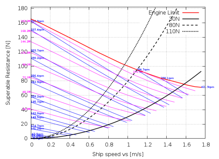
    After determining a propeller open-water curve with CFD (Computational Fluid Dynamics) or another calculation method, a further analysis – especially a Propulsion Analysis – required to reliably predict the propulsion performance for a specific ship. We have developed specialized analysis software solutions that enable seamless integration into the ship design process, relying exclusively on open-source software.

    From the Drift Curve to the Propulsion Analysis

    The Propeller free-running curve (also called the open-water curve) describes the hydrodynamic behavior of a propeller under defined conditions—without the influence of the ship's hull. It provides fundamental performance metrics such as the thrust coefficient (KT), torque coefficient (KQ) and propeller efficiency $(\eta)$ as a function of the advance coefficient $(J)$.

    This curve forms the basis for all further analyses, but by itself is not sufficient to represent the actual Propulsion power in real ship operation to be determined. Only a complete propulsion analysis – taking into account hull resistance, wake, suction, and mechanical losses – can provide a reliable performance prediction.

    Drive analysis: Methodology and calculation steps

    A complete Ship propulsion analysis typically includes the following steps:

    • Resistance prediction: Determination of the total resistance of the ship at a given speed, e.g., by CFD simulation or based on recognized approximation methods (ITTC methods, Holtrop-Mennen).
    • Propeller-Hull Interaction Consideration of discharge coefficient (w), suction coefficient (t), and relative rotational efficiency (η)R).
    • Operating point determination Determination of the operating point of the propeller and engine in interaction (Self-Propulsion Point).
    • Performance Forecast Calculation of required shaft power, including gearbox and bearing losses.
    • Sea-going and fouling surcharges: Addition of practice-relevant surcharges for operation under real conditions (Sea Margin, Fouling Allowance).

    Our open-source-based software solutions

    We have customized Analysis software solutions developed, based exclusively on open-source technologies – transparent, flexible, and cost-efficient. Our tools are designed to integrate seamlessly into existing design processes, whether in the early conceptual stage or during the detailed design phase.

    The advantages of our open-source approach:

    • Transparency and traceability: All calculation steps are openly viewable and scientifically verifiable.
    • Independence from commercial licensing models: No hidden costs, no vendor lock-in.
    • Interoperability Easy integration with common CFD packages (e.g., OpenFOAM) and other design tools.
    • Customizability Full customization to project-specific requirements and ship types.
    • Community and Further Development: Benefit from an active open-source community and continuous improvements.

    Areas of application and ship types

    Our analysis methods are suitable for a wide range of vessel types and application areas, including:

    • Merchant ships (container ships, tankers, bulk carriers)
    • Workboats and offshore supply vessels
    • Ferries and passenger ships
    • Research and Special Vehicles
    • Sports boats and yachts

    Conclusion: Efficient performance prediction in modern ship design

    The combination of precise CFD-based propeller analysis and a structured drive analysis forms today's State of the art in hydrodynamic ship design. With our open-source software solutions, we offer naval architects and design offices a powerful, transparent, and cost-effective tool – from the free-running curve to the final performance prediction.

    Contact us to learn more about our analysis methods and software solutions, or view our case studies and reference projects.